
Synchronous Motor V Curves
The performance characteristics of a synchronous motor are obtained by v-curves and inverted v-curves. Synchronous machines have parabolic type characteristics (the graph drawn is in the shape of parabolic).
If the excitation is varied from low (under-excitation) to high (over-excitation) value, then the current Ia also changes i.e., becomes minimum at unity PF and then again increases.
But at starting lagging current becomes unity and then becomes leading in nature. V-curves and inverted V-curves of a synchronous motor are used to analyze efficiency on no-load and on-load conditions.
The graphs plotted between armature current (Ia) and field current (If) for different constant loads are known as the V curves of the synchronous motor.
V curve is a plot of the stator current versus field current for different constant loads. The Graph plotted between the armature current Ia and field current If at no load the curve is obtained known as V Curve. Since the shape of these curves is similar to the letter “V”, thus they are called the V curve of a synchronous motor.
The power factor of a synchronous motor can be controlled by changing the field excitation, i.e., by variation of field current (If). Also, the armature current (Ia) changes with the change in the excitation or field current (If).
Now, let us assume that the synchronous motor is operating at no-load. If the field current (If) is increased from a small value, the armature current (Ia) decreases until Ia becomes minimum. The power factor of the motor corresponding to this minimum armature current is unity. Up to the point of minimum armature current, the motor was operating at lagging power factor. If a graph is plotted between armature current (Ia) and field current (If) at noload, the lowest curve in Figure-1 is obtained. In order to obtain a family of curves as shown in Figure-1, the above procedure is to be repeated for various increased loads.
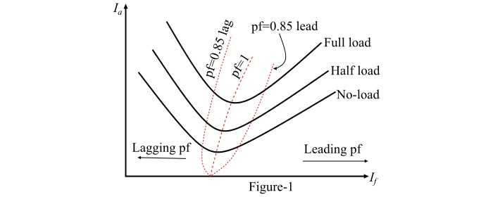
Because the shape of the curves plotted between armature current (Ia) and field current (If) resembles the letter "V", thus these curves are known as V curves of a synchronous motor.
The point corresponding to unity power factor is the point at which the armature current is minimum. The curve connecting the unity power factor points (or lowest points) of all V curves for various loads is called the unity power factor compounding curve. Similarly, the compounding curves for 0.85 power factor lag and 0.85 power factor lead are shown by dotted curves in Figure-1.
Therefore, the compounding curves may be defined as the loci of constant power factor points on the V curves of a synchronous motor. The compounding curves give the information about the manner in which the field current (If) of the motor should be varied to maintain constant power factor under changing loads.
Hence, the V curves are useful in adjusting the field current of the synchronous motor. From the V curves shown in Figure-1, it is clear that decreasing the field current below that for minimum armature current results in lagging power factor. Similarly, increasing the field current beyond the level of minimum armature current results in leading power factor. Therefore, by changing the field excitation of a synchronous motor, the reactive power supplied to or consumed from the power system can be controlled.
Inverted V Curves of Synchronous Motor
Inverted V curves of a synchronous motor are defined as the graphs plotted between power factor and field current (If) of the motor.
A family of inverted V curves of a synchronous motor obtained by plotting the power factor versus field current is shown in Figure-2.
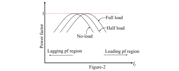
The peak point on each of these curves indicates unity power factor. From the curves, it can be seen that the field current (If) for unity power factor at full-load is greater than the field current (If) for unity power factor at no-load.
The inverted V curves also show that if the synchronous motor at full-load is operating at unity power factor then removal of the mechanical load from the shaft of the motor causes the motor to operate at a leading power factor.
From the inverted V – curve,
- The synchronous motor operates at a lagging power factor when the excitation is under excited.
- The motor operates at a unity power factor at normal excitation.
- The motor operates at a leading power factor when the excitation is over-excited.
A synchronous motor is capable of operating at all types of power factor i.e. either UPF, leading, or lagging power factor.
- Lagging power factor: If field excitation is such that Eb < V the motor is said to be under excited and it has a lagging power factor.
- Leading power factor: If field excitation is such that Eb > V the motor is said to be over-excited and it draws leading current. So that the power factor improves.
- Unity power factor: If field excitation is such that Eb = V the motor is said to be normally excited.


