
Induction Motors
Induction motors are electric motors that use alternating current (AC), propelled by a magnetic field that rotates. They are made up of a rotor, a stator and coils that convert electrical energy into mechanical energy using electromagnetic induction. AC induction motors are highly efficient and flexible, and relatively simple in design, which allows them to match the load demand for almost any electrical application.
An induction motor is the most modest electrical machine from the construction point of view.
Its characteristic features are:
- Simple and rugged construction
- Low cost and minimum maintenance
- High dependability and sufficiently high proficiency
- Needs no additional starting motor and necessity not to be synchronized
Types of induction motors and their applications
Induction motors are categorized into two main types: single-phase and three-phase induction motors. And there are further classifications based on their way of starting.
The single-phase induction motor is not self-starting. A single-phase AC current supplies the primary winding and produces a pulsating magnetic field. These motors are designed to operate from single-phase supply and are manufactured in large quantities for use in homes, offices, factories, etc. There are four types of single-phase induction motors:
- Split Phase Induction Motor
- Capacitor Start Induction Motor
- Capacitor Start Capacitor Run Induction Motor
- Shaded Pole Induction Motor

- Pumps
- Compressors
- Small fans
- Mixers
- Toys
- High-speed vacuums
- Electric shavers
- Drilling machines,
Types of 3 Phase Induction Motor:
Depending upon the type of rotor used the three-phase induction motor is classified as:
- Squirrel Cage Induction Motor
- Wound Rotor or Slip Ring Induction Motor

For squirrel cage type, the rotor winding comprises of uninsulated copper or aluminium bar embedded into semi-closed rotor slots. These solid bar conductors are short circuited at both ends by end ring of same material. Thus this kind of rotor looks like a squirrel cage and hence called Squirrel Cage Induction Motor.
In wound rotor or slip ring induction motor, the insulated windings are wound on the rotor in the same manner as on the stator. This rotor winding is uniformly distributed and generally connected in STAR. The three leads from this STAR connection is taken out through slip ring. This the reason, it is called slip ring induction motor.
| Squirrel cage rotor | Wound or slip cage rotor |
|---|---|
| This rotor is in the form of bars which are shorted at the end with the help of end rings. | This rotor is in the form of 3 phase winding. |
| In squirrel cage rotor no slip rings or brushes. | In wound or slip rotor slip rings and brushes are used. |
| It has a simple construction. | It has complicated construction. |
| External resistance cannot be connected. | It is possible to connect external resistance. |
| It has less rotor copper loss. | It has high rotor copper loss. |
| In squirrel cage rotor resistance starter cannot be used. | In slip cage rotor resistance starter can be used. |
| Application: Used in fans, water, pump etc. | Application: It include in crane, elevators, compressors, lifts etc. |
Three-phase induction motors are used for commercial and industrial purposes, ideal for higher-power applications.
- Lifts
- Cranes
- Hoists
- Large exhaust fans
- Lathe machines
- Crushers
- Oil extracting mills
- Textiles
- Commercial electric and hybrid vehicles
The torque T, of an induction motor, is proportional to the product of stator flux per pole (Φ), rotor current (I), and the power factor of the rotor. The torque of an induction motor is due to the interaction of the rotor and stator fields and is dependent on the strength of the fields and their phase relationship.
Thus,T ∝ I2Cos Φ2Since rotor induced EMF/phase, E is proportional to the stator flux Φ.i.e., E2 ∝ ΦTherefore,T ∝ E2 I2 Cos Φ2But rotor current/phase, and, Rotor Power factor,
 Therefore,
 Where, K = Constant of proportionality = 3*60/2π Ns


Starting Torque :
The torque produced by the motor at the start is called starting torque, Tst. At start, N = 0 and hence slip, s = 1. Therefore, starting torque can be obtained by substituting s = 1 in equation (2), i.e., torque equation under the running condition.

Comparison of Torques :
The performance of the motor is sometimes expressed in terms of comparison of various torques such as full-load torque, starting torque, and maximum torque.
Relation Between Full-load and Maximum Torque :
Letsf = full-load slipThe expressions for full-load torque TFL, and maximum torque, Tmax is, The ratio of full-load torque to maximum torque is,
 Dividing numerator & denominator by X22, we get,


Relation Between Starting Torque and Maximum Torque :
The expression for starting torque Tst, and maximum torque, Tmax are,
 By dividing the numerator and denominator by X22, we get


Torque slip characteristics of an Induction Motor
The Torque Slip Characteristic is represented by a rectangular hyperbola. For the immediate value of the slip, the graph changes from one form to the other. Thus, it passes through the point of maximum torque when R2 = sX20. The maximum torque developed in an induction motor is called the Pull Out Torque or the Breakdown Torque. This torque is a measure of the short time overloading capability of the motor.
The torque slip characteristic curve is divided roughly into three regions. They are as follows:
- Low slip region
- Medium slip region
- High slip region
The torque equation of the induction motor is given below: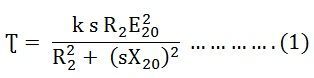
Low Slip Region
At the synchronous speed, s = 0, the torque is zero. When the speed is very near to synchronous speed, the slip is very low, and (sX20)2 is negligible in comparison with R2. Therefore,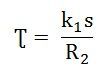 If R2 is constant, the torque becomes
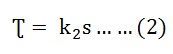
When k2 = k1/R2
From equation (1) shown above, it is clear that the torque is proportional to slip. Hence, in the normal working region of the motor, the value of the slip is small. The torque slip curve is a straight line.
At the synchronous speed, s = 0, the torque is zero. When the speed is very near to synchronous speed, the slip is very low, and (sX20)2 is negligible in comparison with R2. Therefore,If R2 is constant, the torque becomes
When k2 = k1/R2
From equation (1) shown above, it is clear that the torque is proportional to slip. Hence, in the normal working region of the motor, the value of the slip is small. The torque slip curve is a straight line.
Medium Slip Region
As the slip increases, the speed of the motor decreases with the increase in load. The term (sX20)2 becomes large. The term R22 may be neglected in comparison with the term (sX20)2 and the torque equation becomes as shown below:
At the standstill condition, the torque is inversely proportional to the slip.
High Slip Region
Beyond the maximum torque point, the value of torque starts decreasing. As a result, the motor slows down and stops. At this stage, the overload protection must immediately disconnect the motor from the supply to prevent damage due to overheating of the motor.
The motor operates for the values of the slip between s = 0 and s = sM. Where sM is the value of the slip corresponding to the maximum torque. For a typical induction motor, the pull-out torque is 2 to 3 times the rated full load torque. The starting torque is about 1.5 times the rated full load torque.
The curve shown below shows the Torque Slip Characteristic of the induction motor: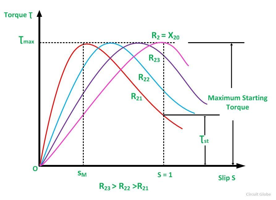
Testing Of Induction ==Motor
Like other machines induction motors are tested to get the necessary information to know parameters, losses, efficiency, speed, torque, current, P.f., etc. The following tests are made on induction motors:
The purpose of these tests is to estimate the performance characteristics of the induction motor. Along with preliminary tests, these tests are also done on motor.
- Direct test
- No-load test
- Blocked (or locked) rotor test
Direct Or Load Test
Another machine like a generator, mechanically coupled with the shaft of the motor acts as a load. The load on the motor is changed by changing the electric load on the generator. The output of the generator and input of the motor are determined by means of various meters connected as shown in Figure.

Direct or load test on 3 Phase induction motor
Let the generator is of DC type. Generator output = V2I2, where V2, I2 are output voltage and current:
Efficiency of generator, ηg = output of generator / Input of generator = V2I2 / input of generator
or
Input of generator = V2I2 / ηg
But input of generator = output of motor = V2I2 / ηg
The efficiency of the motor, ηm = output of motor / Input of motor = (V2I2/ ηg) / W1 + W2 where W1 + W2 = input power to the motor.
The direct test has some disadvantage that is large consumption of power during testing, Also the availability of a load connected to the motor is necessary.
Another machine like a generator, mechanically coupled with the shaft of the motor acts as a load. The load on the motor is changed by changing the electric load on the generator. The output of the generator and input of the motor are determined by means of various meters connected as shown in Figure.
Direct or load test on 3 Phase induction motor
Let the generator is of DC type. Generator output = V2I2, where V2, I2 are output voltage and current:
Efficiency of generator, ηg = output of generator / Input of generator = V2I2 / input of generator
or
Input of generator = V2I2 / ηg
But input of generator = output of motor = V2I2 / ηg
The efficiency of the motor, ηm = output of motor / Input of motor = (V2I2/ ηg) / W1 + W2 where W1 + W2 = input power to the motor.
The direct test has some disadvantage that is large consumption of power during testing, Also the availability of a load connected to the motor is necessary.

Indirect Or No-Load Test
The no-load test of an induction motor determines the friction and windage losses and the magnetization current. The no-load test is carried out with different values of applied voltage. The power input is measured by two wattmeter's, no-load current "Io" by ammeter, and the input voltage "V" by voltmeter which are included in the circuit shown in Figure 2(a). The readings of the total power input "Wo", "Io" and voltage "V" are plotted as shown in Figure 2(b). If we extend the curve for "Wo" it cuts the vertical axis at point A. "OA" represents losses due to friction and windage. If we subtract the loss corresponding to "OA" from "Wo" then we get the no-load electrical and magnetic losses in the machine.

Figure 2: (a) No-Load Test (b) Curves obtained from No-Load test
"OB" represents normal voltage. Hence at normal voltage, the no-load input power "Wo" consists of:
(i) Small stator cu. Loss
(ii) Core loss
(iii) Loss due to friction and windage
These losses can be found from the curve by drawing a vertical line from B.
BD = loss due to friction and windage
DE = stator cu. Loss
EF = Core loss
Knowing the core loss, Go, Bo, and Yo can be determined as
Go = Core loss / 3V2
Yo = Io/V
Bo = √( Yo2 – Go2)
Input power factor angle can also be found from input power:
Wo = √3 VL Io Cos Øo
CosØo =√3 VL Io
Where
VL = Line voltage.
The no-load test of an induction motor determines the friction and windage losses and the magnetization current. The no-load test is carried out with different values of applied voltage. The power input is measured by two wattmeter's, no-load current "Io" by ammeter, and the input voltage "V" by voltmeter which are included in the circuit shown in Figure 2(a). The readings of the total power input "Wo", "Io" and voltage "V" are plotted as shown in Figure 2(b). If we extend the curve for "Wo" it cuts the vertical axis at point A. "OA" represents losses due to friction and windage. If we subtract the loss corresponding to "OA" from "Wo" then we get the no-load electrical and magnetic losses in the machine.
Figure 2: (a) No-Load Test (b) Curves obtained from No-Load test
"OB" represents normal voltage. Hence at normal voltage, the no-load input power "Wo" consists of:
(i) Small stator cu. Loss
(ii) Core loss
(iii) Loss due to friction and windageThese losses can be found from the curve by drawing a vertical line from B.
BD = loss due to friction and windage
DE = stator cu. Loss
EF = Core lossKnowing the core loss, Go, Bo, and Yo can be determined as
Go = Core loss / 3V2
Yo = Io/V
Bo = √( Yo2 – Go2)Input power factor angle can also be found from input power:
Wo = √3 VL Io Cos Øo
CosØo =√3 VL Io
Where
VL = Line voltage.

Blocked Rotor Test
This test is also known as the locked-rotor or short-circuit test. This test is used to find:
- Short circuit current with normal voltage applied to the stator
- P.f. on short circuit
- Total Cu. Losses
- Equivalent circuit elements i.e., total leakage reactance "X01” referred to the stator, and total resistance "R01" referred to the stator.
In this test rotor is locked i.e. it is held stationary by some means. The rotor is short-circuited at slip rings if the motor has a wound rotor. Just as in the case of a short circuit test on a transformer, a reduced voltage (up to 20 percent of normal value) is applied to the stator terminals. This voltage is adjusted so that full load current flows in the stator. As here slip, equal to one, the equivalent circuit of the motor is exactly like a transformer having short-circuited secondary. The values of current, voltage, and power on the short circuit are measured by different meters connected to the circuit.
The following are found from this test:
Short circuit current ISN obtainable with normal voltage "V"
Let:
Zs = Short circuit impedance
Is = Short circuit current with voltage "Vs"
Short circuit current on normal voltage can be found as IsN = IsV / Vs
Power factor on the short circuit:
Ws =√3 VL ISL CosØs
CosØs = Ws / √3 VSL ISL
where
Ws = short circuit input power
VSL = line voltage on short circuit
ISL = line current on short circuit.
Cu. Loss.
Motor input on short circuits consists of mainly stator and rotor Cu. Losses and core losses:
Ws = Ccu + WCL
where Wcu = Total copper losses
WCL = Core losses
Or
Wcu = Ws - WCL
R01, X01, Z01,
From an equivalent circuit diagram of the induction motor
Z01 = Vs/Is
And from total Cu. Losses
Wcu = 3Is2 R01
Or
R01 = Wcu/3Is2
X01 = Root (Z012 – R012)
In the case of the squirrel cage rotor, R1 is determined as usual and after allowing for Skin effect is subtracted from R01 to give the effective rotor resistance R2 as referred to the stator.
R2 = R01 - R1
This test is also known as the locked-rotor or short-circuit test. This test is used to find:
- Short circuit current with normal voltage applied to the stator
- P.f. on short circuit
- Total Cu. Losses
- Equivalent circuit elements i.e., total leakage reactance "X01” referred to the stator, and total resistance "R01" referred to the stator.
In this test rotor is locked i.e. it is held stationary by some means. The rotor is short-circuited at slip rings if the motor has a wound rotor. Just as in the case of a short circuit test on a transformer, a reduced voltage (up to 20 percent of normal value) is applied to the stator terminals. This voltage is adjusted so that full load current flows in the stator. As here slip, equal to one, the equivalent circuit of the motor is exactly like a transformer having short-circuited secondary. The values of current, voltage, and power on the short circuit are measured by different meters connected to the circuit.
The following are found from this test:
Short circuit current ISN obtainable with normal voltage "V"
Let:
Zs = Short circuit impedance
Is = Short circuit current with voltage "Vs"
Short circuit current on normal voltage can be found as IsN = IsV / VsPower factor on the short circuit:
Ws =√3 VL ISL CosØs
CosØs = Ws / √3 VSL ISLwhere
Ws = short circuit input power
VSL = line voltage on short circuit
ISL = line current on short circuit.Cu. Loss.
Motor input on short circuits consists of mainly stator and rotor Cu. Losses and core losses:
Ws = Ccu + WCL
where Wcu = Total copper losses
WCL = Core losses
Or
Wcu = Ws - WCLR01, X01, Z01,
From an equivalent circuit diagram of the induction motor
Z01 = Vs/Is
And from total Cu. Losses
Wcu = 3Is2 R01
Or
R01 = Wcu/3Is2
X01 = Root (Z012 – R012)In the case of the squirrel cage rotor, R1 is determined as usual and after allowing for Skin effect is subtracted from R01 to give the effective rotor resistance R2 as referred to the stator.
R2 = R01 - R1


