
Types of Flip-Flop Circuits
Types of flip-flops:
- RS Flip Flop
- JK Flip Flop
- D Flip Flop
- T Flip Flop
Flip flop v/s Latch
The basic difference between a latch and a flip-flop is a gating or clocking mechanism.
Read the full comparison of Flip Flop v/s latch here
For example, let us talk about SR latch and SR flip-flops. In this circuit when you Set S as active the output Q would be high and Q’ will be low. This is irrespective of anything else. (This is an active-low circuit so active here means low, but for an active high circuit active would mean high)
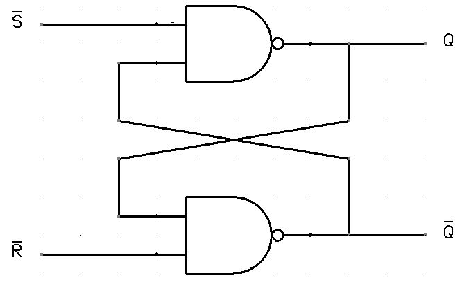
flip flop, on the other hand, is synchronous and is also known as gated or clocked SR latch.
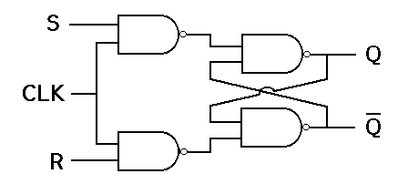
- SR flip-flop: Is similar to an SR latch. Besides the CLOCK input, an SR flip-flop has two inputs, labeled SET and RESET. If the SET input is HIGH when the clock is triggered, the Q output goes HIGH. If the RESET input is HIGH when the clock is triggered, the Q output goes LOW.Note that in an SR flip-flop, the SET and RESET inputs shouldn’t both be HIGH when the clock is triggered. This is considered an invalid input condition, and the resulting output isn’t predictable if this condition occurs.
- D flip-flop: Has just one input in addition to the CLOCK input. This input is called the DATA input. When the clock is triggered, the Q output is matched to the DATA input. Thus, if the DATA input is HIGH, the Q output goes HIGH, and if the DATA input is LOW, the Q output goes LOW.Most D-type flip-flops also include S and R inputs that let you set or reset the flip-flop. Note that the S and R inputs in a D flip-flop ignore the CLOCK input. Thus, if you apply a HIGH to either S or R, the flip-flop will be set or reset immediately, without waiting for a clock pulse.
- JK flip-flop: A common variation of the SR flip-flop. A JK flip-flop has two inputs, labeled J and K. The J input corresponds to the SET input in an SR flip-flop, and the K input corresponds to the RESET input.


